
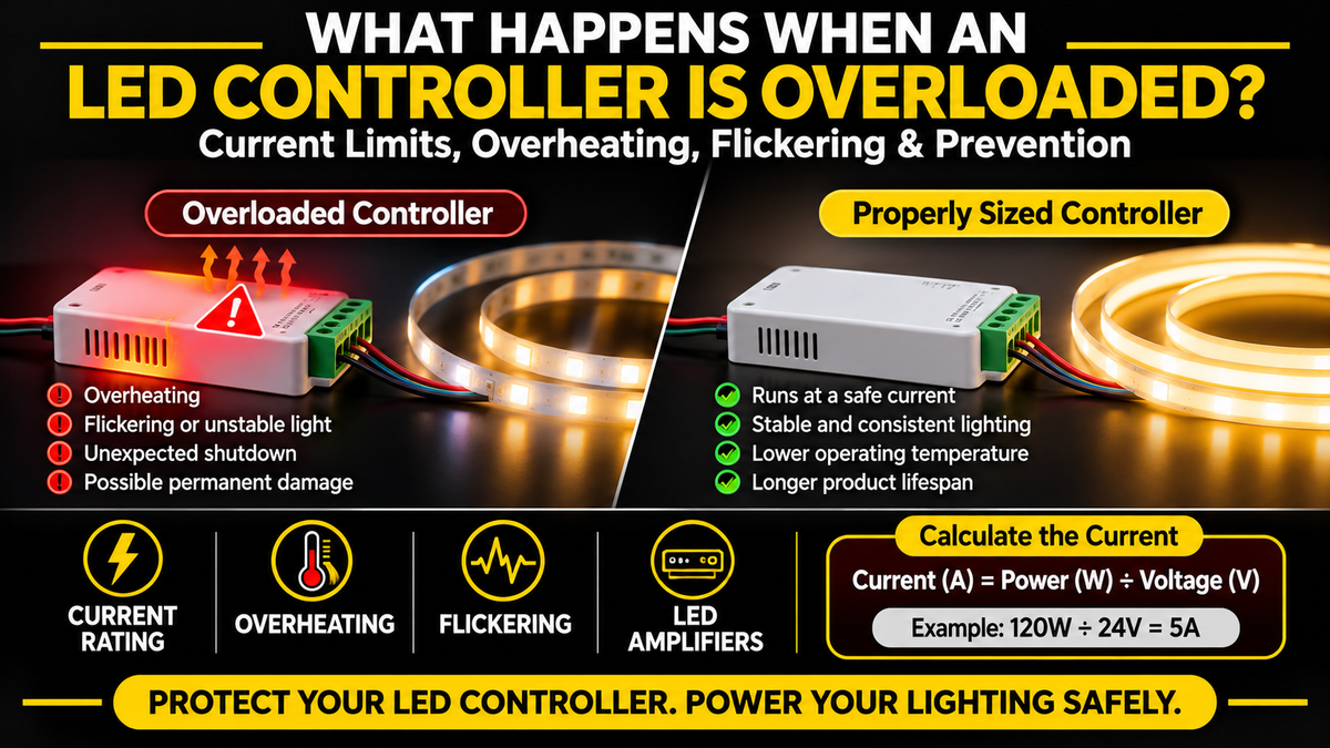
What Happens When an LED Controller Exceeds Its Current Rating?
LED controllers play an essential role in modern lighting systems.
Whether you're controlling a single-color COB LED strip, an RGB installation, or a multi-zone RGB+CCT lighting system, the controller regulates how power is delivered to the connected LED strips.
However, every controller has electrical limits.
One of the most important is its maximum current rating, usually expressed in amperes (A).
If the connected LED strip load exceeds that rating, the controller may overheat, shut down, behave unpredictably, or suffer permanent damage.
In more serious cases, excessive current can damage wiring or create a fire hazard.
Understanding controller current limits is therefore essential for designing a safe and reliable LED lighting system.
In this guide, we'll explain what happens when an LED controller is overloaded, how to recognize the warning signs, how to calculate current requirements, and how to choose the right solution for larger LED installations.
Every product page in our controllers and remotes range publishes both the per-channel and total current ratings, which are the two figures this guide is about.
1. What Is an LED Controller's Current Rating?
An LED controller's current rating indicates the maximum electrical current it is designed to handle under specified operating conditions.
Current is measured in amperes.
For example, a controller might be rated for:
5A per channel
6A per channel
10A total
15A total
20A total
These values are illustrative. Actual specifications vary by model.
Some controllers have separate current limits for each output channel and an additional limit for the entire controller.
Both limits must be respected.
Here are the real ratings across our own range, which show how differently they can be structured:
| Controller | Per Channel | Total |
|---|---|---|
| FUT036S (single colour) | 12A | 12A |
| FUT039 (RGB+CCT) | 6A | 10A |
| WL5 (5-in-1) | 6A | 15A |
| PA5H (amplifier) | 15A | 30A |
Example
Suppose a controller is rated for:
6A per channel
15A total
Connecting a load drawing 7A through one channel would exceed that channel's rating, even if the total current remains below 15A.
Similarly, connecting three channels drawing 5.5A each would result in:
5.5A × 3 = 16.5A
That would exceed the controller's 15A total rating.
Important: A controller must remain within both its individual channel limits and its overall current limit.
That example is not hypothetical in our range — 6A per channel with a 15A total is exactly the WL5's specification.
2. What Happens When an LED Controller Is Overloaded?
The consequences depend on the controller's internal design, protection circuitry, operating temperature, and the severity of the overload.
Not every controller responds in the same way.
A. The Controller May Overheat
One of the most common risks of excessive current is overheating.
As current flows through electronic components, some electrical energy is converted into heat.
The controller's switching components, circuit board traces, connectors, and terminals must be designed to handle this heat.
When current exceeds the rated limit, internal temperatures may rise beyond the intended operating range.
Possible Symptoms
Controller housing becomes unusually hot
Lighting becomes unstable
Controller shuts down after operating for a while
Plastic components become discolored
Electrical connections show signs of heat damage
Why Is This Dangerous?
Excessive temperature can accelerate electronic component degradation.
Severe overheating can damage circuit boards, terminals, and surrounding materials.
If the controller becomes unusually hot, disconnect power safely and investigate the cause before operating it again.
Ambient temperature matters here too: the units in our controllers range specify an operating range of −10°C to +40°C, so a controller buried in an unventilated cabinet is starting from a worse position than one with air around it.
B. LED Strips May Flicker
Flickering is another possible symptom of controller overload.
An overloaded controller may experience unstable switching behavior or activate internal protection circuitry.
This can interrupt the power delivered to the LED strips.
What You Might Notice
Lights flicker at high brightness
Flickering begins when multiple zones operate
Lights become unstable when all RGB channels are activated
Flickering disappears when brightness is reduced
Lights flash or cycle unexpectedly
Important
Flickering does not always indicate controller overload.
It can also result from:
Insufficient driver capacity
Voltage drop
Loose wiring
Poor electrical connections
Incompatible dimming equipment
Faulty LED strips
Controller defects
A proper diagnosis should consider the entire system.
C. The Controller May Shut Down Automatically
Some LED controllers include protection mechanisms designed to respond to excessive current or temperature.
Depending on the model, these may include:
Overcurrent protection
Overtemperature protection
Short-circuit protection
When a protection threshold is reached, the controller may reduce output or shut down.
Example
A lighting system operates normally at 50% brightness.
However, when the brightness reaches 100%, the controller shuts down.
This could indicate that the connected load exceeds a controller or power supply limit.
Important
Not all controllers include the same protection features.
Do not assume a controller will shut down safely before damage occurs.
D. The Controller May Suffer Permanent Damage
If excessive current continues, internal electronic components may fail.
Potentially affected components include:
MOSFET switching devices
Printed circuit board traces
Terminal connections
Internal protection components
Other power-handling electronics
Possible Results
One output channel stops working
The controller no longer responds
The controller remains permanently off
One color channel stays on or off
The controller produces inconsistent output
In some failure modes, a damaged switching component may become short-circuited, causing an output to remain energized.
A damaged controller should not be reused until it has been appropriately evaluated.
The practical consolation is that controllers are sold separately from strips and drivers, so a failed controller means replacing one component rather than the installation — see the controllers range.
E. Wiring and Connectors May Overheat
The controller is not the only component affected by excessive current.
Wires, terminals, and connectors also have current-carrying limits.
An overloaded circuit can produce excessive heating, especially where electrical connections have high resistance.
Common Risk Factors
Undersized wiring
Loose screw terminals
Poorly crimped connectors
Incompatible connectors
Excessive current through a single connection
Inadequate circuit protection
Important
The wiring must be sized and protected for the actual current and installation conditions.
A controller with a high current rating does not automatically make the connected wiring safe.
3. Can an Overloaded Controller Damage LED Strips?
Yes, under certain conditions.
However, the effect depends on the controller's failure mode and the overall circuit design.
For example, an overloaded controller may cause:
Intermittent lighting
Unexpected shutdowns
Loss of dimming control
One color channel remaining on
Electrical damage resulting from a failed controller
Does Excess Current Automatically Make LEDs Brighter?
No.
In a typical constant-voltage LED strip system, the connected LED strip determines how much current it draws at the applied voltage.
A controller does not normally force additional current through a correctly designed strip simply because the controller has a higher current rating.
The overload occurs when the connected load demands more current than the controller can safely deliver.
This distinction is important when troubleshooting LED lighting systems.
4. Why Does an LED Controller Become Overloaded?
Several installation and design mistakes can lead to excessive current.
A. Connecting Too Many LED Strips
Every additional LED strip increases the electrical load.
If too many strips are connected to one controller, their combined current may exceed its rating.
B. Using High-Wattage LED Strips
Some high-output COB LED strips consume significantly more power per foot than lower-output models.
The controller must be selected based on actual electrical consumption.
The spread across our own COB range makes this concrete: the 6.5mm Ultra Slim draws 1.83 W/ft while the 12mm Double-Row draws 7.32 W/ft. On a 10A controller at 24V, that is roughly 130 feet of the first strip but only about 32 feet of the second.
C. Ignoring Per-Channel Current Limits
RGB, RGBW, and RGB+CCT controllers distribute current across multiple channels.
A controller's total current rating does not necessarily mean that one channel can carry the entire amount.
D. Adding More Lighting Without Recalculating
A system may initially operate safely.
However, adding additional strips later can exceed the controller's capacity.
E. Using an Incorrect Power Supply Voltage
Applying a voltage outside the controller's specified range can damage the controller.
It may also damage connected LED strips.
Our 5-in-1 drivers are 12V/24V selectable, so the output must be set to match the strip and controller before the first power-up — see the drivers range.
F. Poor Heat Dissipation
A controller operating near its rated capacity may become hotter when installed inside a poorly ventilated enclosure.
High ambient temperatures can reduce the amount of current some controllers can safely handle.
G. Short Circuits or Wiring Faults
A wiring fault can produce current far beyond the intended load.
This is different from ordinary load overload and may cause rapid damage if protection is inadequate.
5. How to Calculate LED Controller Current
The basic formula for a constant-voltage LED lighting system is:
Current (A) = Power (W) ÷ Voltage (V)
For example, consider a 24V LED strip installation consuming 120W.
Current:
120W ÷ 24V = 5A
The connected load requires approximately 5 amperes at its rated operating conditions.
The controller must be rated to handle this current.
Example: 12V LED System
Suppose a 12V LED strip installation consumes 120W.
120W ÷ 12V = 10A
The same power requires twice the current at half the voltage.
Comparison
| System Voltage | Total Power | Approximate Current |
|---|---|---|
| 12V | 60W | 5A |
| 12V | 120W | 10A |
| 24V | 60W | 2.5A |
| 24V | 120W | 5A |
| 24V | 240W | 10A |
These calculations assume the wattage represents the connected load at the specified voltage.
Key Takeaway
For the same electrical power, a higher-voltage system draws less current.
This can make 24V systems attractive for certain larger LED strip installations, provided every component is compatible.
This is a practical reason our COB range is 24V throughout. Reading the last row of that table against the FUT039's 10A total rating: 240W at 24V is exactly at its ceiling, while the same 240W at 12V would be 20A and twice what it can carry.
6. How to Calculate Current Based on LED Strip Length
LED strips are commonly specified in watts per foot or watts per meter.
To calculate total power:
Total Power = Power per Foot × Total Length
Then:
Current = Total Power ÷ Voltage
Example: 24V COB LED Strip
Suppose an LED strip consumes 4W per foot.
The installation requires 30 feet.
Total power:
4W × 30 = 120W
Current:
120W ÷ 24V = 5A
A controller must support at least the calculated load current, subject to its channel and total ratings.
That worked example is close to a real run: 30ft of our 10mm Indoor Dotless COB at 4.27 W/ft comes to 128W, or about 5.3A at 24V — comfortably inside the FUT036S's 12A rating for a single-colour installation.
What About Multiple Strips?
If three identical 30-foot sections are connected to the same controller output:
120W × 3 = 360W
360W ÷ 24V = 15A
The total load is approximately 15A.
The controller, wiring, driver, and power distribution must all be suitable for this load.
At 15A that installation has outgrown every controller in our range except by amplification — the PA5H carries 15A per channel and 30A total, which is the correct way to handle it.
Important
Long LED strip installations may also require multiple power injection points to manage voltage drop.
A controller's current capacity does not eliminate voltage drop in the strips or wiring.
For those injection points, a 192W Dual-Channel or 288W Triple-Output transformer provides separate terminated feeds from one enclosure.
7. Per-Channel Current vs Total Controller Current
This is one of the most important concepts when choosing an LED controller.
Multi-channel controllers often specify two different current limits.
Per-Channel Rating
The maximum current allowed through an individual output channel.
Total Rating
The maximum combined current allowed through all output channels.
Example
Imagine a five-channel RGB+CCT controller rated for:
6A per channel
15A total
These are hypothetical specifications.
| Channel | Connected Load |
|---|---|
| Red | 3A |
| Green | 3A |
| Blue | 3A |
| Warm White | 4A |
| Cool White | 4A |
| Total | 17A |
Each channel is below 6A.
However, the combined current is 17A, exceeding the 15A total rating.
The controller would be overloaded if all five channels were energized at these levels simultaneously.
Our FUT039 is the clearest real illustration of this gap. It is rated 6A per channel across five channels — which multiplies out to 30A — but its actual total rating is 10A. Reading the per-channel figure alone would overstate its capacity threefold. The WL5, also 6A per channel, is rated 15A total. Two controllers with identical per-channel ratings differ by 50% in what they can actually carry.
Important
Some RGB+CCT controllers use operating modes that limit which channels can be active together.
Calculate the maximum simultaneous load based on the controller's actual operating behavior and manufacturer specifications.
Do not simply add every channel's theoretical maximum without considering how the product operates.
8. Why LED Controllers Sometimes Fail Only at Full Brightness
An LED controller may appear to operate normally at lower brightness settings.
Problems may begin only when the user increases brightness.
Why?
Many LED controllers use pulse-width modulation (PWM) to regulate LED brightness.
PWM changes the proportion of time the output is energized.
At lower brightness settings, the average current and heat dissipation may be reduced.
At full brightness, the connected load can draw its maximum rated current.
Typical Symptoms
Lights work at 30% brightness
Flickering begins around 80%
Controller shuts down at 100%
Controller becomes hot after extended use
What Does This Suggest?
The system may be operating close to or beyond an electrical or thermal limit.
However, the same symptoms can also result from an undersized driver or excessive voltage drop.
Important
PWM outputs can still carry full-amplitude current pulses at reduced brightness.
Therefore, operating at lower brightness should not be used as a substitute for proper controller sizing.
This is worth emphasising, because it is a tempting workaround. A system that only misbehaves at 100% is not a system that has been fixed by being run at 70% — it is an undersized controller or driver that has not yet failed.
9. Can a Larger LED Driver Prevent Controller Overload?
Not necessarily.
A common misconception is that installing a more powerful LED driver automatically solves controller overload.
The driver and controller have different responsibilities.
LED Driver
Provides the required electrical voltage and sufficient power to the lighting system — see our drivers and transformers.
LED Controller
Regulates the electrical output delivered to the LED strips — see our controllers and remotes.
Example
Suppose you have:
24V LED strips consuming 240W
A 24V, 300W driver
An LED controller rated for only 5A total
The strip current is:
240W ÷ 24V = 10A
The driver may have sufficient power capacity.
However, the controller is rated for only 5A.
The controller remains overloaded.
Built from our range, that system would pair the 300W 5-in-1 driver with a controller rated for at least 10A — the FUT039 at exactly 10A, or the WL5 at 15A for headroom.
Does a Bigger Driver Force More Current Through the Controller?
No.
In a properly operating constant-voltage system, the connected load determines current demand.
A higher-capacity driver does not automatically force its maximum rated current through the controller.
However, the system must still have appropriate circuit protection because a higher-capacity power source may be capable of supplying substantial fault current.
10. What Is a Safe Current Margin for LED Controllers?
For reliable operation, it is often sensible to avoid designing a controller system to operate continuously at its absolute maximum rating.
For some installations, a design margin of approximately 20% may be useful.
However, this is a general engineering guideline, not a universal manufacturer requirement.
Example
Suppose the calculated LED strip load is 8A.
Using a 20% design margin based on controller capacity:
8A ÷ 0.8 = 10A
A controller rated for at least 10A may provide an appropriate starting point.
In our range, 10A total is the FUT039 exactly — so an 8A colour installation sits right at the edge of that margin, and the WL5 at 15A would be the more comfortable specification.
Why Allow Extra Capacity?
Additional capacity may help accommodate:
Manufacturing tolerances
Variations in operating conditions
Higher ambient temperatures
Future system changes
Thermal design considerations
Important
Always follow the manufacturer's actual ratings, temperature derating requirements, and installation instructions.
A controller specifically rated for continuous full-load operation may not require an arbitrary additional margin.
11. How to Prevent LED Controller Overload
Step 1: Calculate the Total LED Strip Wattage
Multiply the rated power per unit length by the total connected length. Watts per foot is published on every page in our strip range.
Step 2: Calculate the Required Current
Divide total power by the rated system voltage.
Step 3: Check the Controller's Per-Channel Rating
Confirm that no individual output channel exceeds its specified limit.
Step 4: Check the Total Controller Rating
Confirm that the maximum simultaneous current remains within the total rating. As section 7 shows, this is the figure most often missed.
Step 5: Verify the LED Driver
Make sure the driver provides the correct voltage and sufficient power.
Step 6: Check Wiring and Connectors
Confirm that wires and connectors are suitable for the current and installation conditions.
Step 7: Consider Thermal Conditions
Avoid installing controllers in environments that exceed their specified operating temperature range.
Step 8: Use Additional Power Control Hardware When Necessary
For larger installations, consider a compatible LED amplifier or multiple appropriately designed controller circuits — our amplifier is the PA5H.
12. What Is an LED Amplifier?
An LED amplifier, sometimes called an LED signal amplifier or repeater, allows a compatible lighting system to control additional LED strip loads.
Instead of routing all LED strip current through one controller's outputs, a suitable amplifier can use a separate power input to drive additional LED strip sections.
The original controller provides the control signal.
The amplifier handles the electrical load connected to its outputs.
Example
Imagine a large RGB+CCT installation with several LED strip sections.
One controller may not have sufficient current capacity to power every section directly.
A compatible multi-channel amplifier can help distribute the electrical load while maintaining coordinated control.
Our PA5H is the five-channel amplifier for this: 15A per channel, 30A total, 12–24V DC, with 10Mbps signal transmission to keep its output synchronised with the main controller. Its five channels match an RGB+CCT system exactly, and it also covers RGBW, RGB, CCT and single-colour PWM systems.
Advantages
Supports additional LED strip loads
Reduces current passing through the original controller outputs
Can simplify expansion of larger installations
Allows synchronized lighting control when correctly configured
Important
Not every amplifier works with every controller.
Compatibility depends on:
Control method
Number of channels
Voltage
PWM signal characteristics
Electrical connections
Amplifier current ratings
The PA5H uses a common-anode connection and is specified as compatible with MiBoxer controllers and other common-anode PWM controllers — the FUT039 is named as a compatible accessory. Check the connection type before pairing an amplifier with any controller.
An amplifier does not automatically increase the original controller's current rating.
It provides additional output capacity through its own properly rated power circuit.
13. When Should You Use an LED Amplifier?
Consider an amplifier when:
The connected load exceeds the controller's output rating
Multiple LED strip sections must operate together
A large commercial lighting installation requires synchronized control
Additional lighting sections are being added to an existing system
The controller has sufficient control capability but insufficient power-handling capacity
Example
Suppose a controller is rated for 10A total.
Your planned installation requires 18A.
Rather than forcing 18A through the controller, a compatible amplifier arrangement may allow the load to be divided between appropriately rated output circuits.
The exact wiring configuration depends on the controller and amplifier specifications.
That example maps directly onto our range: 10A total is the FUT039, and 18A is well beyond it but inside the PA5H's 30A total. In practice the FUT039 keeps the control and the PA5H carries the load, with its own driver sized to that load — which at 18A and 24V means roughly 430W, so more than one 384W unit or a split supply.
Safety Note
Do not connect two independently powered controller or amplifier outputs directly together unless the manufacturer explicitly permits that arrangement.
Improper connections can damage equipment.
14. Can One Controller Operate Multiple LED Amplifiers?
In some systems, yes.
A compatible controller may provide a control signal to multiple amplifiers.
This can be useful for:
Large retail displays
Long architectural lighting installations
Multiple shelving sections
Commercial decorative lighting
Multi-section RGB or RGB+CCT projects
What Must Be Verified?
Controller output compatibility
Amplifier input compatibility
Maximum supported signal loading
Wiring arrangement
Power supply capacity
Electrical isolation requirements
Grounding or common-reference requirements
Manufacturer installation instructions
Important
The ability to connect multiple amplifiers depends on the specific product design.
Do not assume every LED controller supports unlimited amplifiers.
15. How to Troubleshoot an Overloaded LED Controller
If your LED lighting system is flickering, shutting down, or overheating, use a systematic troubleshooting process.
Step 1: Turn Off the Power
Disconnect the system before inspecting wiring or changing connections.
If there are signs of overheating, damaged insulation, smoke, or burning odor, do not re-energize the system until it has been professionally evaluated.
Step 2: Check the Controller Specifications
Identify:
Rated voltage
Per-channel current limit
Total current limit
Maximum output power
Operating temperature limits
All five are published on each product page in our controllers range.
Step 3: Calculate the Connected Load
Determine the maximum expected current for every channel.
Step 4: Check the Driver
Verify that the driver voltage matches the system and that it has adequate output capacity.
Step 5: Inspect Wiring
Look for:
Loose terminals
Discoloration
Damaged insulation
Incorrect connections
Undersized wiring
Incompatible connectors
Step 6: Reduce the Connected Load for Testing
A qualified person may isolate part of the installation and test a smaller load under controlled conditions.
If the system becomes stable with less load, this may indicate a capacity-related problem.
However, it does not conclusively prove that the controller is the only issue.
Step 7: Check Operating Temperature
Evaluate whether the controller is operating within its specified temperature range.
Step 8: Replace or Redesign the System
If the controller is undersized, select a suitable higher-capacity model or redesign the installation using compatible amplifiers and power distribution.
16. LED Controller Overload vs LED Driver Overload
These problems can produce similar symptoms but have different causes.
| Feature | Controller Overload | Driver Overload |
|---|---|---|
| Main issue | Controller output current exceeds rating | Power supply load exceeds rating |
| Possible overheating | Controller | Driver |
| Flickering | Possible | Possible |
| Shutdown | Possible | Possible |
| Channel-specific failure | Possible | Less typical |
| Main solution | Correct controller sizing or amplification | Correct driver sizing |
| Electrical checks | Per-channel and total current | Voltage, wattage, and output current |
Key Point
A properly sized driver does not compensate for an undersized controller.
Likewise, a high-current controller cannot compensate for an inadequate driver.
Both components must be selected correctly.
They are separate purchases for this reason — the drivers range runs from 30W to 384W, and the controllers range from 10A to 12A with the PA5H at 30A above them.
17. Common Mistakes That Lead to Controller Overload
Mistake 1: Looking Only at Wattage
Controller current ratings must also be considered.
Mistake 2: Ignoring Voltage
The same wattage requires different current at 12V and 24V.
Mistake 3: Exceeding Per-Channel Limits
A multi-channel controller may be overloaded on one output even when its total rating is not exceeded.
Mistake 4: Adding More LED Strips Without Recalculating
Every expansion changes the connected load.
Mistake 5: Assuming a Larger Driver Solves Everything
The controller must independently support the required current.
Mistake 6: Ignoring Heat
Controllers installed in hot or enclosed spaces may require derating.
Mistake 7: Using Undersized Wiring
Wiring and connectors must safely carry the expected current.
Mistake 8: Assuming Protection Circuits Prevent All Damage
Overcurrent and thermal protection vary by controller.
Mistake 9: Using Incompatible Amplifiers
Incorrect amplifier selection can cause malfunction or damage. Check the connection type — our PA5H is common-anode.
Mistake 10: Continuing to Operate a Controller That Overheats
Repeated overheating can increase the risk of permanent damage.
18. Quick Decision Summary
| Situation | Recommended Action |
|---|---|
| Controller becomes unusually hot | Turn off power and inspect the system |
| Lights flicker only at high brightness | Check controller and driver capacity |
| One color channel stops working | Check channel load, wiring, and controller condition |
| Total load exceeds controller rating | Select a suitable controller or amplifier arrangement |
| One channel exceeds its rating | Reduce or redistribute that channel's load |
| Driver is powerful but controller is undersized | Upgrade controller capacity |
| Multiple LED strips must operate together | Consider compatible amplification |
| System shuts down repeatedly | Check overload, overheating, and wiring faults |
| Controller shows burn marks or damaged terminals | Do not reuse until professionally evaluated |
| Planning a new installation | Calculate current before selecting components |
The Bottom Line: A controller must be rated for the maximum current its connected LED strips can draw. Both per-channel and total limits matter.
Translated into our range: single-colour installations up to 12A use the FUT036S; colour installations up to 10A the FUT039, or the WL5 up to 15A; and anything beyond that the PA5H at 30A, driven by whichever controller suits the lighting type.
19. Professional LED Controller Sizing Checklist
Before connecting LED strips to a controller, confirm:
LED strip voltage matches the controller.
Driver output voltage is correct.
Total LED strip wattage is calculated.
Maximum current is calculated.
Per-channel current limits are respected.
Total controller current remains within rating.
Driver output capacity is sufficient.
Wiring is appropriately sized.
Connectors are rated for the expected current.
Suitable circuit protection is provided.
Controller ventilation meets manufacturer requirements.
Dimming and color-control compatibility are confirmed.
Amplifier compatibility is verified if used.
Voltage drop has been considered.
Manufacturer installation instructions are followed.
Voltage range, per-channel current, total current and operating temperature are published on every page in our controllers and remotes range, and watts per foot on every page in the strip range.
Frequently Asked Questions
1. What happens if an LED controller exceeds its current rating?
The controller may overheat, flicker, shut down, behave unpredictably, or suffer permanent damage. The exact result depends on its design and protection features.
2. Can an overloaded LED controller catch fire?
Severe electrical overheating can create a fire hazard, particularly when wiring or connections are inadequate. Proper sizing and circuit protection are essential.
3. How do I know if my LED controller is overloaded?
Possible signs include overheating, flickering, shutdowns, unstable color control, and failures that occur at higher brightness settings.
4. Can an LED controller be overloaded even if the driver is powerful enough?
Yes. The controller and driver have separate electrical ratings.
5. What does 6A per channel mean?
It means an individual output channel is rated to carry up to 6 amperes under the manufacturer's specified conditions. Check the total rating separately — our FUT039 is 6A per channel but 10A in total.
6. What does total current mean on an LED controller?
It is the maximum combined current allowed across the controller's outputs, and it is usually lower than the per-channel rating multiplied by the number of channels.
7. Can I connect more LED strips to a controller if I dim them?
Dimming should not be used to justify exceeding the controller's specified electrical limits.
8. Does a 24V LED strip draw less current than a 12V strip?
For the same electrical power, a 24V system draws half the current of a 12V system. Our COB range is 24V throughout.
9. Can a controller shut down when overloaded?
Yes, some controllers include protection circuitry that can reduce output or shut down under certain fault conditions.
10. Will an overloaded controller damage LED strips?
It can, depending on how the controller fails and the electrical conditions of the system.
11. Can I use a bigger LED driver to fix controller overload?
Not by itself. The controller must also have adequate current capacity.
12. What is an LED amplifier?
An LED amplifier is a compatible device that uses a control signal to drive additional LED strip loads through its own rated output circuit — see the PA5H at 15A per channel and 30A total.
13. Can one LED controller work with multiple amplifiers?
Some systems support this configuration, but compatibility and wiring requirements must be verified.
14. Is it safe to run an LED controller at maximum current?
Only when the controller is rated for the intended operating conditions and installed according to the manufacturer's instructions. A 20% margin is a sensible default.
15. Why does my controller get hot at full brightness?
Higher load current can increase internal heat generation. Excessive temperature may indicate overload, poor ventilation, or another fault.
16. Why does my RGB controller flicker when all colors are on?
The combined channel load may exceed the controller or driver capacity. This is the per-channel versus total distinction in section 7. Wiring faults and voltage drop are also possible causes.
17. Can one channel fail while the others still work?
Yes. Individual output components can fail independently.
18. Do LED controllers have overload protection?
Some do, but protection features vary by model. Always check the manufacturer's documentation.
19. How do I calculate the current of an LED strip?
For a constant-voltage system, divide the strip's rated power in watts by its rated voltage. Watts per foot is on every page in our strip range.
20. What is the best way to prevent controller overload?
Calculate the maximum connected load, verify both channel and total current ratings, use suitable wiring and drivers, and add compatible amplification when necessary.